🎉 Celebrating 25 Years of GameDev.net! 🎉

Not many can claim 25 years on the Internet! Join us in celebrating this milestone. Learn more about our history, and thank you for being a part of our community!

Math problem with circular image (radians, not evenly spaced?)

Started by
18 comments, last by suliman 4 years, 3 months ago

Hi!

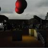
I have a function (see below) where float2 is a simple class holding a x and y float. I use the function to draw a circular image:

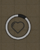
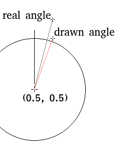
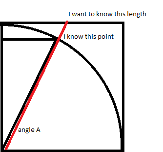
This is drawn with the variable “progress” at value 0.1 (the dark part is 10 % of a full lap). The problem is that something is off, if i evenly increase “progress” the filling of the image is faster in cardinal directions (north, east etc) and slower in the “corners” (northeast etc). The image is a square so it seems the code below goes around the other border of that square or something ( it needs to “go further” in the corners of the image). Any idea? I just want the increase to look smooth and fill the image “the same speed” no matter where in the circle im adding to the variable “progress”.

Thanks!

	float2 p[4];
	float rad = progress * PI2;

	p[2] = float2(sin(rad), -cos(rad));
	p[2].x *= sqrt(2.0) * 0.5;
	p[2].y *= sqrt(2.0) * 0.5;
	p[2].x += 0.5;
	p[2].y += 0.5;
	clamp(p[2].x, 0, 1);
	clamp(p[2].y, 0, 1);

	if (progress < 0.25)
	{
		p[0].set(0.5, 0);
		p[1].set(1, 0);
		p[3].set(0.5, 0.5);
	}
	else if (progress < 0.5) {

		p[0].set(1, 0.5);
		p[1].set(1, 1);
		p[3].set(0.5, 0.5);
		gfx.picPartRel(x + pic->GetWidth()*0.5*scale, y, pic, 0.5, 0, 0.5, 0.5, 0, scale, color, colorMode, 0, z);
	}
	else if (progress < 0.75) {
		p[0].set(0.5, 1);
		p[1].set(0, 1);
		p[3].set(0.5, 0.5);
		gfx.picPartRel(x + pic->GetWidth()*0.5*scale, y, pic, 0.5, 0, 0.5, 1.0, 0, scale, color, colorMode, 0, z);
	}
	else {
		p[0].set(0, 0.5);
		p[1].set(0, 0);
		p[3].set(0.5, 0.5);
		gfx.picPartRel(x + pic->GetWidth()*0.5*scale, y, pic, 0.5, 0, 0.5, 1.0, 0, scale, color, colorMode, 0, z);
		gfx.picPartRel(x, y + pic->GetHeight()*0.5*scale, pic, 0, 0.5, 0.5, 0.5, 0, scale, color, colorMode, 0, z);
	}

	pictureFourPoints(x, y, p, pic, scale, color, colorMode, z);
Advertisement

I don't understand the ‘if’ code at all, but why don't you draw a filled triangle for the area between the start angle and end angle (probably only the last ¼, as areas of 90 degrees can be filled simpler), and then apply a mask that gives you only the circle?

Alternatively, if you can draw the gray/green inner circle and outer area afterwards, you can draw that on top of the filled area.

Ok I need to add info ?
The four points (p) is for the quarter of the image that is a non-rect part of the full image.
"picPartRel" drawn a rect of the image.

For example the last “else”-section (when image is between 75 and 100 % full) first drawns the clock from 12 to 6 oclock. Then draws 6 to 9 oclock (so there is two calls to “picPartRect” function). And the “pictureFourPoints” draws the remaining part of the clock (from 9 to full lap 12 depending on the value of “progression”.

So the issue is in how i set up the 4 points in the beginning, since the clock fills slower in the corners (example: 1:30 oclock) than in the cardinal directions (for example 3:00 oclock).

A picture with the rectangle that you draw would have helped ?

I think the problem is with ‘clamp’. If the angle is mostly pointing up your y is moved down, but x is not moved in the same way, ie your angle changes (moves towards the corner). If you draw the resulting line on a piece of paper for a few angles, you'll likely see fairly quickly happening what you describe.

To keep the angle the same, you need to compute x if you clamp y and vice versa.

EDIT: Alternatively, compute x with tan (ie length of orthogonal line opposite of the corner with an angle.)

Make a vid showing what you get and what you want so we could show you easier solution that hundreds of else ifs

Dont know how to record my screen as a video sorry. The rectangle image used is seen below (it can be any rect image of course this happen to be a ring (the black rectangle is just there to show the borders of the image).

If the if-cases confuses you just look at the first one (progress <0.25). The unevenness comes from how the moving point p[2] is set up. The point “moves” along the other rectangle border (with constant speed) when progress increases, while it should be relative to the increase in progress (the angle in percent).

Apparently a picture is needed:

In the picture, I drew the real 15 degrees angle, and the angle that you draw after clamping y. As you can see, the drawn angle is larger than the real angle. This increase gets smaller when abs(y-clamp(y)) gets smaller, and is 0 at 45 degrees. Obviously this effect gets mirrored between 45 and 90 degrees, where you clamp x rather than y.

Let's name the vertical distance from the center v, the horizontal distance from the center h, and the length of the line with an angle a.

The fix is not to clamp, but to use “tan(angle)” which is v/h by definition, with v = 0.5 . This works until 45 degrees angle, at which point you basically swap x and y, to avoid tan() running to infinity at 90 degrees.

Thanks!

I fixed it (the speed is now smooth all along the circle, no “speed-ups”). Now i just need to enlong the point so it's sits on the rectangle outline and not follow along the circle (doesnt matter when i have transparancy in my picture like the one above but matters when I want to “clock-draw” a filled picture (see example from red alert 2 below, it can be considered a top image (clear image) that is “clock-drawn” at 35 % progression)).

Mathematically i just need to get the length from the unit-circle to the rectangle-border. I can then enlong the point with that factor. So how long is that distance if the angle is 0° to 90° ? (it 1 at 0° and 90° and sqrt(2) at 45°).

Pythagoras: a*a = h*h + v*v

Yes I know but how would I apply it here? I know all 3 lengths of the small triangle (in the circle) but i dont know the point where the “large tringle” would hit the “bounding box” (outer rectangle) if the line from the centre would be prolonged. I know that line is of length 1, but what is the length of the red line (see pic below).

This topic is closed to new replies.

Advertisement